

Brufik Desktop Robot

Brufik Desktop Robot
Overview
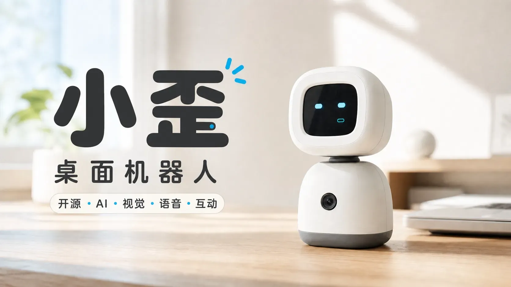
Brufik is an open-source desktop robot with an expressive display, a camera, audio input and output, and two servos for head movement. This Thorb replication follows the V2 hardware and is supplied as a DIY parts kit.
Both PCBs are supplied with their board-mounted components assembled. You complete the mechanical assembly, firmware flashing and computer setup. The display adapter PCB and the LCD module are separate items in the parts list.
Interaction and control
- Expressions, audio and head movement work together through the selected software.
- The current upstream Windows or macOS client connects the robot to the configured model and voice services.
- USB is the primary connection; the upstream instructions also describe a local-network connection.
- You configure your own API keys. Available features and service charges depend on your chosen providers.
- Links to the original hardware, printable structure and software remain available for building and learning.
This is a DIY hardware kit. Assembly, flashing and software configuration are carried out by the builder. Features depend on the installed software version and configuration.
Hardware and appearance
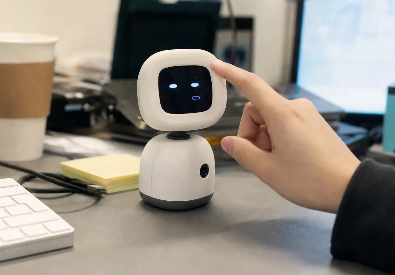
The gallery shows the original robot and a desktop interaction scene, with source credits. All seven print groups use PLA Basic in black, white, gray, red, yellow, blue or orange. The base and head-to-body shaft default to gray; the others default to white. Exterior parts remain CNY 3 in their default color or CNY 5 in another color. The separate shaft costs CNY 1 in gray or CNY 1.60 otherwise. The internal pack excludes the shaft and costs CNY 4 in white or CNY 6.40 otherwise. These two items total CNY 5 in default colors or CNY 8 when both use non-default colors; all default printed parts total CNY 20. Colours in upstream photos are references.
The printed-parts group has seven lines: head front frame, head back frame, body front shell, body back shell, base, head-to-body shaft and internal structure pack. The internal pack combines the remaining frames, gears, brackets and pins, excluding the separately listed head-to-body shaft.
V2 parts and assembly
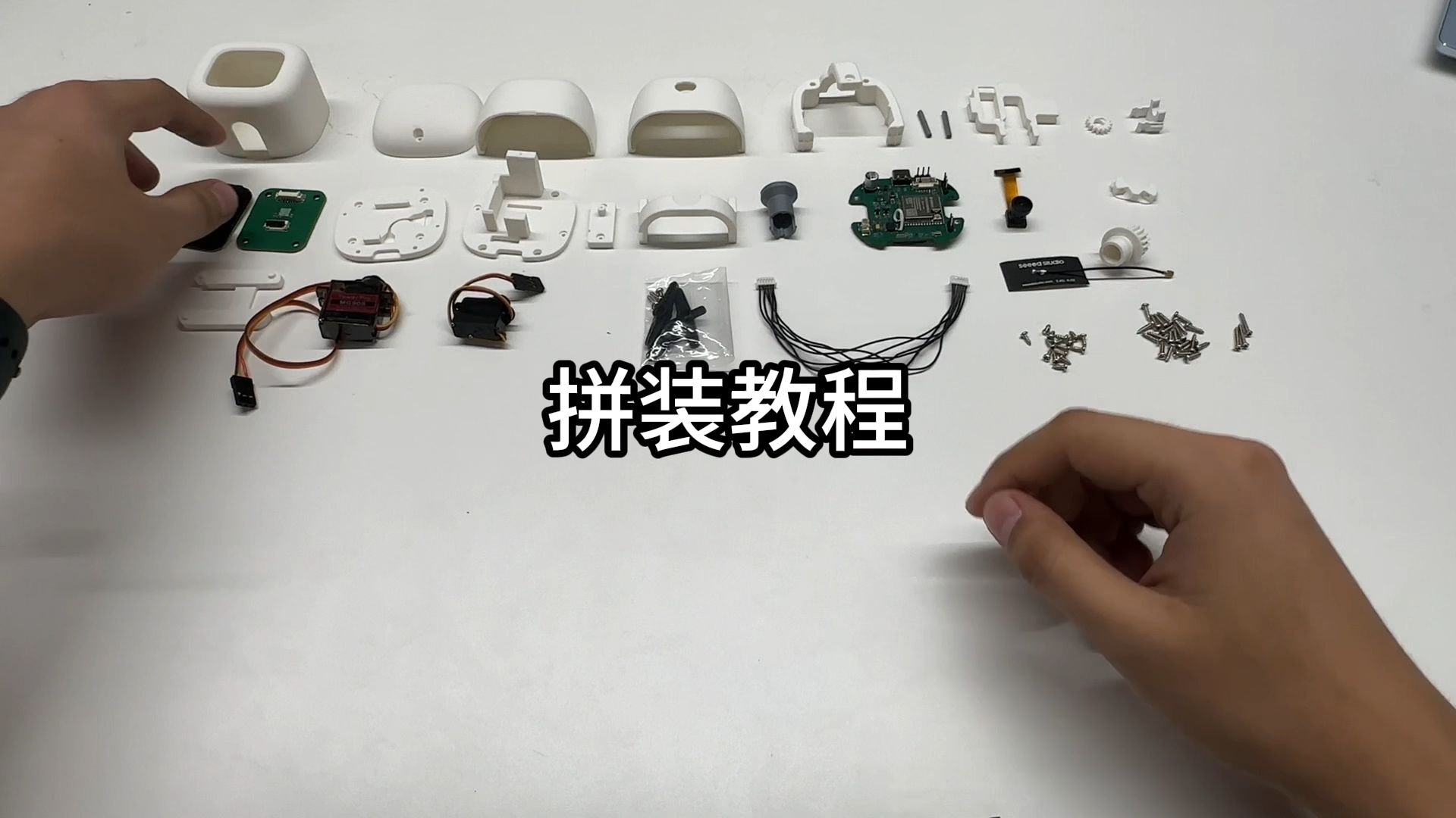
The build combines an ESP32-S3 main PCBA, a display adapter PCBA, a 1.83-inch LCD, an OV3660 camera, two servos, a speaker, an antenna and connecting cable with printed structural parts and fasteners. The Kit parts list defines the quantities and options.
Use the matching 12-pin, non-touch LCD and the V2 camera configuration. The display cable is a 150 mm, 1.25 mm-pitch, 6-pin cable with matching connector orientation. Board-mounted components are already included in the assembled PCB items.
Original assembly video
The 11:59 tutorial by tobey0612 covers the display, head structure, body, wiring and enclosure. It does not cover software installation or flashing. Use it alongside the V2 assembly PDF and this Kit’s parts list. The board revision visible in the video has not been confirmed as identical in every detail to the October BOM.
Open the upstream V2 assembly PDF
Tools and supplies
The assembly guide calls for a Phillips screwdriver, scissors, a small file, double-sided tape and 502 adhesive. Some steps involve trimming a servo horn, cleaning up printed surfaces and applying a very small amount of adhesive. Read the complete guide before starting.
The USB-A male to USB-C male data cable (0.5m, specified for 5V 2A and data transfer), single USB-A 5V 2A power adapter, adhesive, tape and tools are optional paid additions, default quantity 0. Bring your own or select them in the optional-supplies group.
The robot has one USB-C port. When powered by the adapter, use a configured Wi-Fi connection to a computer running the client; initial flashing still requires a USB data connection. The adapter model and CCC certificate match, 2A operation and cable voltage drop remain subject to supplier and first-sample verification.
Earlier versions
This Kit follows V2. The original project retains V1 material as a historical reference; V1 parts, wiring and older software instructions are not the default build instructions for this Kit.
Computer client
Current OpenDeskBotV2 software and setup instructions
Follow the upstream Windows or macOS instructions to configure the device, model and voice services. A new board requires the complete initial flashing procedure. Follow the documentation for the installed version when updating it later.
How the system connects
The robot hardware captures audio and images, displays expressions and drives the servos. The computer client connects the device to the configured model and voice services and returns the response to the robot. Prepare a compatible computer and your service accounts before setup.
Main specifications
| Item | V2 reference |
|---|---|
| Main module | ESP32-S3-WROOM-1U-N16R8, following the Base V2 BOM |
| LCD | 1.83-inch, 240 × 284, ST7789-series controller, 12-pin, non-touch |
| Camera | OV3660, opposite-side configuration, 120°, 40 mm; matching Kit option required |
| Motion | One 9 g 180° servo and one 3.7 g servo |
| Speaker | 2011 enclosure, 8 Ω, 1 W, 1.25 mm 2-pin connector |
| Main PCB | Base V2.0, four layers, assembled on both sides with the specified headers |
| Display PCB | LCM V2.0, two layers, assembled on one side |
| Software | Current upstream Windows/macOS client with your own model and voice configuration |
Getting started
- Check the Kit list, printed parts and servo accessories against the V2 guide.
- Assemble the display, head, body and enclosure, checking cable orientation and moving parts.
- Use a USB data cable and follow the current upstream instructions for the complete initial firmware flash.
- Install the computer client, connect the robot, configure your services and test audio, display, camera and movement.
Open source and credits
Original design: Brufik on OSHWHub, by eda_hedwaytj. Software: OpenDeskBotV2. Thorb organises the replication materials and build references and retains upstream credits.
The current upstream licence summary assigns CERN-OHL-S-2.0 to the structure, PCBs, schematics and BOM, and GPL-3.0 to the firmware and PC service. Third-party components retain their own licences. The upstream installer includes miloco-miot under a separate non-commercial-use licence. Image sources are credited separately.
Questions
Does the display PCB include the screen? The assembled display PCB is an adapter. The LCD module is a separate part, and the build uses both.
Is this a finished robot? It is a DIY materials kit requiring assembly, flashing and software setup.
Do I need a computer and API services? The current software uses a computer client and services configured by the builder. Those services may charge separately.
Can I follow the older tutorials? Prefer the V2 PDF and current software documentation. V1 instructions, old demo servers and older chip specifications do not define this Kit.
Why buy a kit
Building from the BOM means finding every part in a different shop, and getting the circuit board made and the case printed yourself. We put the parts together for each project. You can buy only what you are missing, or have us assemble, flash and test it for you.
See the kits you can buy- Original author
- Original project: eda_hedwaytj / OpenDeskBot. Thorb curates the V2 DIY kit and assembly resources. Hardware, software and third-party components retain their respective upstream licences.
- License
- CERN-OHL-S-2.0
- Original project
- oshwhub.com
If you believe something here infringes your rights, email bd@thorb.com and we will reply within 5 working days.
Reviews
Log in to mark reviews as helpful. Customers who have received this project can write reviews and replies.Log in
No reviews yet.